Handley Page Slots
- Handley Page Slots App
- Handley-page Slot
- Handley Page Slots Online
- Handley Page Victor
- Handley Page Slots Free
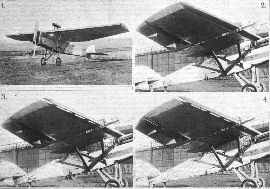
Handley Page slots on the leading edge of the wing outer panels, plus trailing-edge flaps, made possible a low landing speed. Somewhat cramped accommodation was provided for a crew of four. The Handley Page Gugnunc was specifically designed to compete in the Guggenheim Air Safety competition. Some of the requirements for the $10,000 prize (in 1929) were a stall speed no greater than 35 mph, top speed of 110 mph, an engine-off glide ratio of greater than 10:1 and 400 fpm climb. Handley Page British Patent No. 172,109, also relied upon in this connection by the defendant, covered the multi-slotted wing which preceded the invention of the slotted trailing-edge flap. This patent does not claim the same invention as the patent in suit. Slots were first developed by Handley Page in 1919 and the first aircraft to fly with them was the experimental H.P.17, a modified Airco DH.9A. The first aircraft fitted with controllable slots was the Handley Page H.P.20. Licensing the design became one of Handley Page’s major sources of income in the 1920s. Part of the work completed by Handley Page during the early 1920s, in an attempt to satisfy a standing Fleet Air Arm (FAA) requirement of 1920 for a modern carrier-based torpedo bomber, was the 'Hendon'.
Download PDFInfo
- Publication number
- US1433030A US1433030AUS469402AUS46940221AUS1433030AUS 1433030 AUS1433030 AUS 1433030AUS 469402 AUS469402 AUS 469402AUS 46940221 AUS46940221 AUS 46940221AUS 1433030 AUS1433030 AUS 1433030A
- Authority
- US
- United States
- Prior art keywords
- sections
- slots
- Page Frederick Handley
- Current Assignee (The listed assignees may be inaccurate. Google has not performed a legal analysis and makes no representation or warranty as to the accuracy of the list.)
- Handley Page Slots App
- Original Assignee
- Priority date (The priority date is an assumption and is not a legal conclusion. Google has not performed a legal analysis and makes no representation as to the accuracy of the date listed.)
- Filing date
- Publication date
- CriticalHandley Page Ltd
- Criticalpatent/US1433030A/en
- Priority claimed from US581822Aexternal-prioritypatent/US1496731A/en
- Application grantedgrantedPublication of US1433030ApublicationAnticipated expirationlegal-statusExpired - Lifetimelegal-statusCurrent
- description2
- description2
- description1
- description1
- description1
- description1
- description1
- description1
- B—PERFORMING OPERATIONS; TRANSPORTING
- B64C—AEROPLANES; HELICOPTERS
- B64C21/02—Influencing air-flow over aircraft surfaces by affecting boundary-layer flow by use of slot, ducts, porous areas, or the like
- B—PERFORMING OPERATIONS; TRANSPORTING
- B64C—AEROPLANES; HELICOPTERS
- B64C2230/06—Boundary layer controls by explicitly adjusting fluid flow, e.g. by using valves, variable aperture or slot areas, variable pump action or variable fluid pressure
- B—PERFORMING OPERATIONS; TRANSPORTING
- B64C—AEROPLANES; HELICOPTERS
- B64C2230/20—Boundary layer controls by passively inducing fluid flow, e.g. by means of a pressure difference between both ends of a slot or duct
- Y—GENERAL TAGGING OF NEW TECHNOLOGICAL DEVELOPMENTS; GENERAL TAGGING OF CROSS-SECTIONAL TECHNOLOGIES SPANNING OVER SEVERAL SECTIONS OF THE IPC; TECHNICAL SUBJECTS COVERED BY FORMER USPC CROSS-REFERENCE ART COLLECTIONS [XRACs] AND DIGESTS
- Y02T—CLIMATE CHANGE MITIGATION TECHNOLOGIES RELATED TO TRANSPORTATION
- Y02T50/10—Drag reduction
- 1921-05-14USUS469402Apatent/US1433030A/ennot_activeExpired - Lifetime
Links
Images
Classifications
Description
F. H. PAGE.
WING FOR AIRCRAFT. APPLICATION FILED MAY 14. 1921.
Patented Oct. 24, 1922.
Patented Get. 24, 1922.
narrate stares earner (EFF-11GB,
FREDERICK HANDLEY PAGE, OF LONDON, ENGLAND, ASSIGNOR T0 i=i LIMITED, 0]? LONDON, ENGLAND.
WING FOR AIRCRAFT.
Application filed May 14, 1921. Serial No. 469,402.
T 0 all whom it may concern: I
Be it known that I, FREDERICK HANDLEY PAGE, a subject of the King of Great Britain, residing at London, England, have invented certain new and useful Improvements in Wings for Aircraft, of which the following is a specification.
In the specification of United States Patent'No. 1353666, dated 21st September. 1920, an invention has been described in which a slot or slots is or are formed in the leading portion of a wing extendin in a direction transverse to the direction of flight, in order to admit of the passage of air from the under side to the upper side, so as to prevent the burbling effect which takes place with wings when inclined to the air at a large angle of incidence, and by prevention of that burbling permitting the wings to be flown at still greater angles, and greatly improved lift coeflicient being thereby obtained.
Ina wing having slots of this kind, the wing has been considered as composed of a main wing and one or more auxiliary wings set in front of the leading edge thereof, and it has been stated in the specification that the auxiliary wings are set at a less angle of incidence than the main wings. Thus if there is a difierence in angle of 30 between the chord of the main wing and the chord of the auxiliary wing, and the main wing happens to be at an angle of incidence of plus 10, then the angle of incidence of the auxiliary wing would be minus 20.

ccording to the present invention a wing structure for aircraft is composed of a plurality of wing sections each of wing form extending transversely to the longitudinal axis of the machine, one wing section being' located rearward of the otherfrom the leading edge to the trailingedge of said wing structure; a plurality of curved rails are provided, extending transversely of said -wing sections, and one of said wing sections is fixed to the said rails. Means are then provided for slidab'ly connecting the other wing sections composing the wing structure to the said curved rails, to permit said slid able wing sections curved rails. 7
Means are also provided for-sliding said movable'wing sections upon said rails relatively to said fixed wing section and to each to be slidden upon said other, to cause said wing sections to be brought into contactwith each other or to be separated from each other to form comparatively narrow through slots between the said wing sections, each slot extending in a direction transversely of the line of flight, and when so separated to cause said wing structure to be of greater chord than when said wing sections are in contact with each other and said slots closed. When said wing sections are separated from each other, the openings of said slots on the under side of the wing structure are in advance of the openings of said slots on the upper side of the wing structure, all such wing sections whether closed together or separated combining to make up the contour of a whole wing structure, in which portions of the surfaces of each wing section are contained in the contour line surrounding said wing structure.
The term wing section is to be understood as a wing of comparatively high aspect ratio having leading and trailing edges, while the term wing structure used in this specification is to be understood as a structure comprising two or more of such wing sections arranged in tandem from the leading edge to the trailing edge of the wing structure, and all the said wing sections,'
Handley-page Slot

and is influenced by them, and each wing section is masked by the wing section immediately preceding it, and is also at a greater angle ofincidence than the wing sections preceding it. Thus in a wing divided into say five wing sections the leading section may be at an angle of say minus40 the next section at minus 25 the next at minus 10 the next at plus 5 and the last at plus 20.
These examples of relative angles of ,incidence are given not as suitable relative angl'es ofthe wing sections but as an explana tion of the terms referred to.
The invention will be further described with reference to the accompanying drawings. Figs. 1 and 2 are views showing a construction in which the wing sections are so mounted the wing structure as to per-- mit of angular adjustment simultaneously with bodily displacement of the wing sections.
Referring to the drawings, the wing sections 1 are slidable in direction with the lever 12, the ends of the rods 13 being pivot rails, and means for sliding said movable o -curved rails 11 from the ally connected near the trailing edges of the wing sections 1 forward of the lever 12, and being pivotally connected near the leading edges of the wing sections 1 rearward vof the lever 12. Obviously there may be a plurality of such levers 12, and whether tliere is one lever 12 or a plurality, said lever or levers is or are mounted upon a shaft 14,
by the-angular adjustment of which shaft 14 the wing sections 1 will be slidden on the osition shown at Fig. 1 where the wing sections are in contact with each other, to the position at Fig. 2 where the wing sections are separated to form slotsr between themselves and. also where the chord of thewing structure is increased.
VVhat I claim as my invention and desire to secure by Letters Patent is 1. A wing .structure for aircraft, comprised by a plurality of wing sections each of wing form and all extending transversely to the direction of flight, one located rearward .of the other from the leading edge to the trailing edge of said wing structure, a
plurality of curved rails extending transversely of said wing sections, means for fix-' 'mg one of said wing sections'to said rails, means for slidably connecting the other wing sections composing the wing structure to sa d curved rails to permit said slidable wing sectlonsto be slidden upon said curved wing sections upon said rails relatively to said fixed wing section and to each other to cause-said wing sections to be brought into contact with each other or to be separated from each other to form comparatively narrow through slots between said wing sections each slot. extending in a direction tranversely of the line of flight and when so separated to cause said wing structure to be two-arme said slots closed, the openings of said slots on the under side of said wing structure being located in advance of the openings of said slots on the upper side of said wing structure, all said wing sections whether closed together or separated being contained within contour lines of wing forms surrounding said wing structure.
2. A wing structure for aircraft, comprised by' a plurality of wing sections each of wing form and all extending transversely to the direction of flight, one located rearward of the other from the leading edge to the trailing edge of said wing structure, a plurality of curved rails extending transversely of said wing sections, means for fixing one of said wing sections to said rails, means for slidably connecting the other wing sections composing the wing structure to said curved rails to permit said slidable wing sections to be slidden upon said curved rails, and a two armed lever, a pivot connecting said two-armed lever to said fixed wing section, connecting rods pivoted to the upper arm of said two-armed lever and pivoted to the trailing edges of said wing sections forward of said lever, and connecting rods ivoted to the lower arm of said 5 lever extending rearwardly and pivoted to the leading edges of said wing sections rearward of said two-armed lever for sliding said movable wing sections upon said rails relatively to said fixed wing section and toeach other to cause said wing sections to be brought into contact with each other or to be separated from each other to form comparatively narrow through slots between said wing sections each slot extending in a direction transversely of the line of flight and when so separated to cause said wing structure to be of greater chord than when said wing sections are in contact with each other and said slots closed, the openings .of said slots on the under side of said wing structure being located in advance of the openings of said slots on the upper side of said wing structure, all said wing sections whether closed together or separated being contained within contour lines of wing forms surrounding said wing structure.
In witness whereof I have hereunto set my hand in the presence of two witnesses.
FREDERICK HANDLEY PAGE.
Witnesses:
THOMAS WILLIAM Rooms, WILLIAM A. MARSHALL.-
Priority Applications (1)
Publications (1)

| Application Number | Priority Date | Filing Date | Title |
|---|---|---|---|
| US469402AUS1433030A (en) | 1921-05-14 | 1921-05-14 | Wing for aircraft |
| US581822AUS1496731A (en) | 1921-05-14 | 1922-08-14 | Wing for aircraft |
| Publication Number | Publication Date | ||
|---|---|---|---|
| US469402AExpired - LifetimeUS1433030A (en) | 1921-05-14 | 1921-05-14 | Wing for aircraft |
Country Status (1)
Handley Page Slots OnlineHandley Page Victor
Cited By (4)
| Country | Link | |||
|---|---|---|---|---|
| US2423803A (en) * | 1943-12-08 | 1947-07-08 | Edward A Stalker | High lift device |
| US2550850A (en) * | 1943-05-10 | 1951-05-01 | Muller Jaques | Variable incidence multiple wing system for aircraft |
| Publication number | Priority date | Publication date | Assignee | Title |
|---|---|---|---|---|
| US2423803A (en) * | 1943-12-08 | 1947-07-08 | Edward A Stalker | High lift device |
| US6905092B2 (en) | 2002-11-20 | 2005-06-14 | Airfoils, Incorporated | Laminar-flow airfoil |
Handley Page Slots Free
Similar Documents
Latest Posts
| Publication | Publication Date | Title |
|---|---|---|
| US3463418A (en) | Vortex generator for airplane wing | |
| US2444293A (en) | Gap seal for flaps | |
| US2846165A (en) | Aircraft control system | |
| US1871396A (en) | Means of reducing the fluid resistance of automobile bodies | |
| US3478988A (en) | Stol aircraft having by-pass turbojet engines | |
| US2406475A (en) | Slotted airplane wing | |
| US2086085A (en) | Aircraft control gear | |
| US5961068A (en) | Aerodynamic control effector | |
| US3092354A (en) | Aerodynamic system and apparatus | |
| US2123096A (en) | Aeroplane | |
| US2670910A (en) | Aircraft | |
| US2557522A (en) | Aerodynes equipped with reaction jet propulsion means | |